

SMD Quartz Crystal Selection Guide (2016 vs 3215 vs 3225) | MCU & RTC Design
Table of Contents
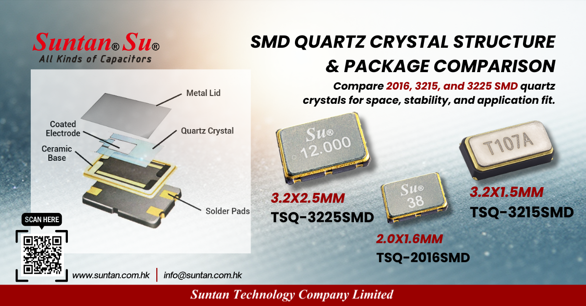
SMD Quartz Crystal Engineering Know-how: 2016 vs 3215 vs 3225 for MCU and RTC Design
This engineering note focuses on practical oscillator margin, ESR limits, and CL implementation when selecting
2016, 3215, and 3225 SMD quartz crystals.
The goal is to reduce startup failures, frequency drift, and field intermittence in MCU and RTC domains.
1. Oscillator domain determines crystal structure
MCU high-speed clocks (HSE) typically use AT-cut MHz crystals,
while RTC low-speed clocks (LSE) use 32.768 kHz tuning-fork crystals.
These are not interchangeable due to different motional resistance, drive level, and load sensitivity.
- HSE design priority: startup margin, ESR headroom, layout parasitic control
- LSE design priority: CL accuracy, ultra-low drive level, noise isolation
2. ESR and startup margin considerations
Oscillator startup requires sufficient negative resistance from the MCU oscillator circuit.
A common engineering rule is:
|Rneg| ? 5 × ESR
Smaller packages such as 2016 tend to have tighter ESR margins and higher sensitivity to PCB parasitics.
For low-drive oscillators, 3225 provides more stable startup behavior.
3. Load capacitance (CL) implementation
For RTC crystals, incorrect CL is the primary cause of time drift.
Effective CL is determined by:
CL = (C1 × C2) / (C1 + C2) + Cstray
Where Cstray includes MCU pin capacitance and PCB parasitics (typically 1–3 pF).
Mismatch between the specified CL and actual implementation shifts frequency and increases current consumption.
4. Package selection engineering comparison
| Package | Typical Use | Engineering Advantage | Primary Risk |
|---|---|---|---|
| 2016 | Compact MCU RF modules | Minimal PCB footprint | Lower startup margin, layout sensitive |
| 3215 | RTC 32.768 kHz | Optimized for ultra-low power | CL mismatch and noise coupling |
| 3225 | Industrial MCU clock | Higher ESR margin, robust startup | Larger footprint |
5. PCB layout guidelines
- Keep crystal loop area minimal and symmetric
- Place load capacitors close to MCU pins
- Use a clean ground reference without via interruption
- Avoid routing near high-speed or switching traces
- Do not place guard rings that add parasitic capacitance
6. Validation workflow for production reliability
Recommended validation steps:
- Measure startup time across temperature and voltage corners
- Verify oscillation amplitude and steady-state frequency
- Check RTC current consumption for CL mismatch indication
- Perform EMI susceptibility test near switching regulators
7. Practical selection summary
- Use 3225 when oscillator margin and industrial robustness are priorities
- Use 2016 only when space is constrained and ESR requirements are verified
- Use 3215 exclusively for 32.768 kHz RTC designs with correct CL matching
Conclusion
Crystal selection is an oscillator stability decision rather than a mechanical choice.
Verifying ESR margin, implementing correct CL, and controlling layout parasitics are essential
to prevent intermittent oscillation and long-term drift in both MCU and RTC domains.